Sequence Diagram
Overview
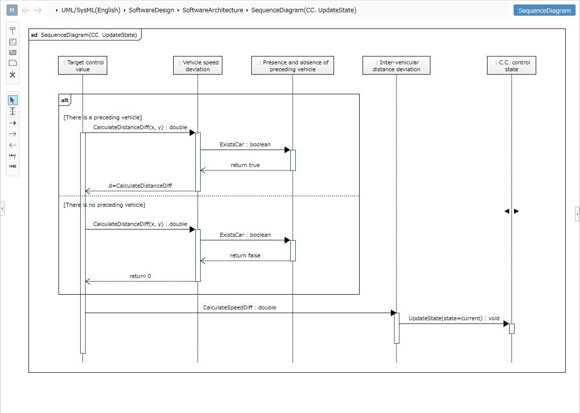
You can use a sequence diagram to visualize the flow of mutual processing between objects.
This page explains the operations for using sequence diagrams in the following order:
- Placing a sequence diagram
- Defining lifelines
- Defining messages
- Defining composite fragments
- Defining interaction usage
The following functions are also provided to assist users in modeling.
These will also be explained in order:
- Validating the model
- Setting the display content
Placing a sequence diagram
To place a sequence diagram, follow the steps below.
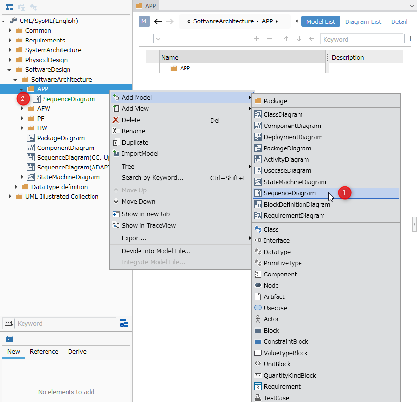
- Select a package in the Model Navigator and click [Add Model] > [Sequence Diagram] from the context menu.
- The sequence diagram will be placed as a child element of the selected package.
Defining a Lifeline
To define a lifeline, follow these steps:
- Select an existing class in the Model Navigator and drag and drop it onto the sequence diagram.
- A new lifeline with the selected class as its type will be created in the displayed sequence diagram.
:::note: Elements that can be added from the Toolbox
The following elements displayed in the Toolbox can be added to sequence diagrams.
| Icon | Name |
|---|---|
| Lifeline | |
| Compound Fragment | |
| Interaction Use | |
| Interaction Note | |
| Destruction |
:::
Define an Untyped Lifeline
You can create an untyped lifeline by dragging and dropping [Lifeline] from the Toolbox onto a sequence diagram.
To change a lifeline's type, select it on the sequence diagram and click Change Lifeline Type in the context menu.
Available Lifeline Types
The following elements can be specified for a lifeline's type:
| Icon | Name |
|---|---|
| Class | |
| Interface | |
| Component | |
| Actor | |
| Block |
Define a Message
To define a message, follow these steps:
- In a sequence diagram, hover the mouse over a lifeline to display a filled triangle icon.
- Drag and drop the icon onto the target lifeline.
- When the finder appears, select the operation corresponding to the message and click the [OK] button.
- A synchronous message is created for the target lifeline.
The following elements, displayed in the Sub Toolbox, can be added to a sequence diagram.
| Icon | Name |
|---|---|
| Synchronous Message | |
| Asynchronous Message | |
| Reply Message | |
| Create Message | |
| Destroy Message |
To add these messages, select the desired message type in the sub-toolbox and then add the message.
:::note: About Message Text Notation
When you enter message operation text on a sequence diagram, the text is parsed according to the message operation notation format.
Of course, changing the values of each field will reflect the changes in the text on the diagram.
Message Text Format and Correspondence Between Field Values
Messages are displayed and parsed according to the following format.
- For request messages (other than response messages)
<Request message> ::= <Message name> ['('[<List of arguments>] ')'] [':'<Return value type>]- supplement
<List of arguments>is displayed in the following format.<List of arguments> ::= <Arguments> [','<Arguments>]*<Argument> ::= [<Argument name> '='] <Argument value> | '-'
- Example
Message name:Drive
Argument 1 name:m, value:100
Argument 2 name:s, value:200
Return type:boolean
In this case, the following text will be displayed.
Drive(m=100, s=200) : boolean - Note
<return type>is ignored when setting.
- supplement
- For response messages
<Response message> ::= [<Return value variable name> '='] <Message name>['(' [<List of arguments>] ')'] [':' <Return value>]- supplement
<List of arguments>is displayed in the following format.<List of arguments> ::= <Arguments> [','<Arguments>]*<Argument> ::= [<Argument variable name> '='] <Argument name> [':' <Argument value>]
- Example
Return value variable name:return_value, return value:true
Message name:Drive
Argument 1 variable name:miles, argument name:m, value:200
Argument 2 variable name:speed, argument name:s, value:100
In this case, the following text will be displayed.
return_value=Drive(miles=m:200, speed:s=100) : true
- supplement
:::
To change the operation associated with a message, select the message and click Change Message Type in the context menu.
Define composite fragment
To define a composite fragment, follow these steps:
- Select a combined fragment in the Toolbox and drag and drop it onto the sequence diagram.
- Double-click the upper left corner of the added combined fragment to display a drop-down list of types, allowing you to select the type of combined fragment you want to add.
The following types can be set for combined fragments:
| Change Shape Type | Meaning |
|---|---|
| alt | Alternative |
| opt | Option |
| loop | Loop |
| par | Parallel |
| break | Break |
| neg | negation |
| strict | strict |
| seq | seq |
| ignore | ignore |
| consider | Consider |
| assert | Assert |
Defining an Interaction Use
To define an interaction use, follow these steps:
- Select the interaction use in the Toolbox and drag and drop it onto the sequence diagram.
- Select the added interaction use and associate it with the referenced sequence diagram using the Interaction Association context menu.
To jump to the sequence diagram associated with an interaction use, select the interaction use and click [Show Associated Interactions] in the context menu.
Validating a Model
The following items are validated in a sequence diagram:
- Whether the operation associated with a message is available in the destination lifeline type.
For example, this tool can detect inconsistencies between the operation associated with a message and the destination lifeline type resulting from the following changes:
- For the operation associated with a message, specify an operation defined in the class that inherits from the class that will become the destination lifeline type.
- In a class diagram, etc., remove the inheritance relationship of the class that will become the destination lifeline type.
To validate a model, follow these steps:
- From the ribbon, select [UML] > [Validation] > [Check Consistency].
- If an inconsistency is detected in the messages placed on the sequence diagram, an error will be displayed.
Clicking the [Home] > [Model] > [Check Error] button on the ribbon will perform validation on the entire model in addition to the standard validation.
Setting Display Content
You can display only the information you are interested in in a sequence diagram without modifying the model.
To set the display content for arguments corresponding to a request message, follow the steps below.
- Display the sequence diagram you want to switch display.
- Check or uncheck the Argument checkbox in the Request Message group on the UML Diagram tab in the Inspector.
You can switch the display of the following elements in a sequence diagram.
| Category | Element |
|---|---|
| Request Message | Argument |
| Argument Name | |
| Return Type | |
| Response Message | Argument |
| Argument Value | |
| Argument Assignment Variable | |
| Return Value | |
| Return Value Variable |
Restrictions
- State invariants and duration constraints cannot be defined.
- Messages cannot be connected from frames.
- Messages cannot be connected to interaction uses.
- Elements cannot be copied and pasted.
- The message order in a sequence (commonly known as GeneralOrdering) is represented only by the Y coordinate on the diagram. When using the difference comparison function, you cannot check the differences as a model.
- Stereotypes are not represented on sequence diagrams.
- Changes to message mapping settings for a sequence diagram will not be reflected in model validation (message mapping error checks), and errors may be detected incorrectly or, conversely, errors may not be detected.
- Model validation is performed according to the default metamodel structure provided by the UmlSysml package before any changes were made.